
Passive Intermodulation (PIM) has over the years become a critical parameter in component design due to new technologies in wireless communications allowing the use of higher transmit powers, wider bandwidths, and multiband / combination antennas.
PIM lowers capacity and data rate by limiting receive sensitivity, and as wireless usage grows pressure is on operators to squeeze the most out of their spectrum.
Passive intermodulation is a form of intermodulation distortion that occurs in passive components such as antennas, cables, connectors, or duplexers with two or more high-power input signals.
This distortion is typically cased by the interaction between mechanical components, especially where two different metals are in close proximity. Junctions of dissimilar metals are a prime cause, but also caused by corrosion, loose connections, dirt, or the presence of nearby metal objects like cable ties, guy wires, brackets, and so on.
Definition of Passive Intermodulation
Passive intermodulation is the low level signal created as the result of multiple high power transmit signals in an antenna. This relatively low power signal is generated at a new distinct frequency and has the potential to inject interference in the receive band thereby degrading the uplink reception.
An intermodulation product is defined as any unwanted frequency resulting from intermodulation between carriers or harmonics of emission.
Specification Definition
When disclosing passive intermodulation on test reports and datasheets, Powertec follow the BASTA reporting recommendations:
- An absolute parameter.
- Specified as a maximum in-band value in dBc (decible carrier: power relative to known power of carrier c).
- 3rd order passive intermodulation products measured using 2 x 20 W (2 x 43 dBm) carriers (F1 and F2).
- 3rd order products are defined at frequencies of (F1 +/- 2*F2) and (F2 +/- 2*F1) falling within the receive band when transmit frequencies F1 and F2 are used as the input carriers.
- Specification shall reference the full frequency range, full electrical downtilt range, and associated ports of the antenna unless specifically detailed otherwise (example: 1695 to 2200 MHz; 0°-10°; +45 and -45 ports).
Testing & Reporting
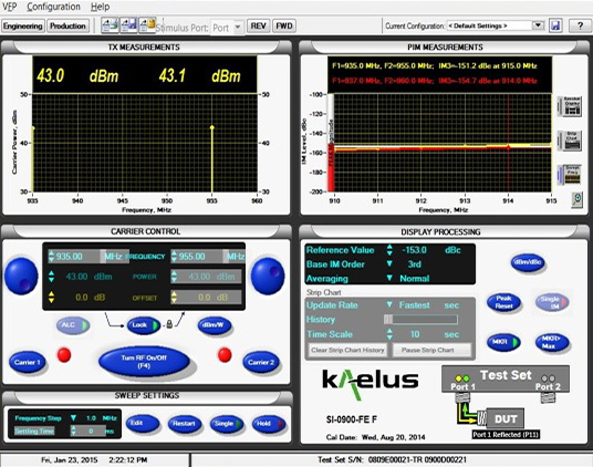
PIM testing is conducted by all reputable manufacturers using specialised PIM testing equipment such as Kaelus PIM Analyser. Field PIM testing will not be discussed in this article. There are two types of PIM testing, Reflective/Reverse PIM Testing, and Forward PIM Testing.
Reflective/Reverse PIM Testing
Reverse, or reflective, PIM testing is the most commonly used type of PIM test. This test sends two signals to an antenna and uses the same test port to capture and measure any intermodulation products. While simpler, a key downside to this type of testing is that results are affected by the antenna cable length which can invalidate test results if performed at fixed frequencies.
Forward PIM Testing
Forward PIM testing with antennas involves measuring the signal transmitted through the antenna system under test. This requires an external receive antenna installed in an anechoic chamber, and spectrum analyzer.
General PIM Testing Requirements
PIM measurement shall be in accordance to the following:
- IEC 62037-6 Passive RF and microwave devices, intermodulation level measurement - Part 6: Measurement of passive intermodulation in antennas defines the test fixtures and procedures for testing PIM
- Measurement shall be performed under condition such that radiated power is not reflected back into the antenna, and that other radiated power cannot be received through the antenna
- Connectors shall be clear of debris and void of damage.
- Power shall be verified at the end of the test cable to ensure appropriate carrier power is fed to the antenna under test. If not done, the test cable loss could mask the true PIM levels.
- Equipment noise floor shall be validated/calibrated using a low-PIM load.
- Measurement shall performed in swept mode (with one of the two tests tones sweeping in frequency).
- Dynamic stress shall be placed on the antenna during PIM testing
- Measuring PIM performance in the sub-band nearest to the middle frequency of the entire bandwidth is generally sufficient to characterize the PIM performance for the whole cluster
References
- NGMN, "Recommendations on Base Station Antenna Standards", NGMN Alliance, N-P-BASTA v11.1, Mar. 2019.
- Keysight, Passive Intermodulation (PIM), [Online], Available: http://www.keysight.com/main/application.jspx?cc=AU&lc=eng&ckey=2127060&nid=-33157.0.00&id=2127060
- Anritsu, Passive Intermodulation (PIM), [Online], Available: https://www.anritsu.com/en-US/test-measurement/technologies/pim